


- PRODUCTS LIST

RAⅢ Selection Manual
 Download
1. Summarizing
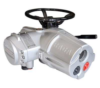
 The newly RAⅢ range electric actuator offers many specially performances. The all actuator operational parameter setting is effected using the non-intrusively, hand held, infra-red setting tool. The torque, valve position, position limit setting and alarm information about actuator are displayed on the liquid crystal display with the way of Chinese, digital and graphics (see to figure 1-1), it can provides many conveniences to user during operating actuator. Available highly class of the watertight enclosure in actuator even if remove the terminal box cover in the field as long time while operating actuator. The actuator can structures the distributed control system with the fieldbus card for remote control , data transmission and maintenance. The RAⅢ range actuators are large-scale applied to the petrol industry, the power station, the metallurgy and the water treatment industries etc for the high reliability and flexibility.
2. Actuator specification
2.1 Input signals:
4mA~20mA;1VDC~5VDC;
2mA~10mA;0.5VDC~2.5VDC;
24VDC pulse or voltage signal;
2.2 Power supply:
380VAC/50Hz
220VAC/50Hz
2.3 Valve controlling error ≤±1%
2.4 Travel controlling mechanism repeatability error ≤3%
2.5 Dead zone: 0.1~9.9% of the total travel
2.6 Watertight enclosure: IP68
2.7 Anti explosive mark: ExdⅡCT4
2.8 Ambient temperature: -30℃~+70℃
2.9 Ambient humidity: ≤95%
3. Actuator features
 3.1 Actuator working theory (see to figure 3-1)
The working theory of actuator is that the motor drives the worm and the gear to rotate, and then the gear drives the output shaft to rotate by the clutch. While the electric/hand level switch to hand position, the clutch is divorced from the gear and coupled with the handwheel and then the output shaft can be drove by the handwheel. Electric operation always has the higher priority than manual operation, when motor is energized that the operation state automatic switch to electric operation mode unless electric/hand lever is purposely locked into ‘manual operation. The valve position measure by a position sensor that is drove by the feedback shaft.
3.2 Function features
 3.2.1 Double-sealed
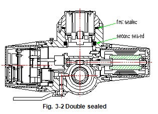
All RAⅢ actuators are housed double-sealed watertight enclosure to completely protect the internal equipment against the dust and the humidity even if the terminal box cover is removed as long time in the field. Refer to figure 3-2. The type of waterproof actuator can running 48 hours while the actuator immerge into water deep 3 meters, but does not mistake the actuator can running with long time that immerged into water. This feature just only provides a short time protection while happening the accident. In addition, user has the responsibility to ensure the sealed of the cable entry.
3.2.2 Non-intrusive design
The RAⅢ electric actuator Non-intrusive design represents two parts. First, the operation knob employs magnetic induction mode switch to instead of the shaft penetrating the shell of the knob (see to figure 3-3 and Fig. 3-4). Second, the actuator operational parameter setting is effected by using the non-intrusively, hand held, infra-red setting tool. The non-intrusive design feature provides many excellences, such as avoid opening the electric cover in the field, debugging actuator in the rain or hazardous locations and quickly check the actuator state etc.

3.2.3 Protection features
3.2.3.1 Torque protection
A sensor serve as overload protection for the entire valve travel, and you can setting a different torque volume between 30~100% of rated torque.
3.2.3.2 Limit protection
Set this function is availability, the actuator should stop automatically while the valve position reach the limit position
3.2.3.3 Automatic phase correction:
Actuator monitor the phases and run in the correct direction regardless of the sequence of power supply connection that is realized through a phase rotation correction Boolean logical calculation.
Without this function that will damage the valve in unconsciously.
3.2.3.4 Instant reversal protection
The motor control logic introduces a delay in switching the motor as a response to instant reversal of control signals, preventing contact damage to the contactors and wear to the gear and the worm.
3.2.3.5 Phase failure protection
Actuator real time monitor all three phases of the power supply during operation to prevent lose phase action.
3.2.3.6 Valve stick motion
Electronic latching inhibits the actuator torque protection function within 5 seconds and allows the motor to generate torque in excess of rated torque to enable operation of jammed valves while starting operation signal is enabled, should the actuator stall when attempting to unseat a valve stuck in its seat, the motor will be de-energised to preventing damage.
3.2.3.7 Motor thermal protection
Two thermostats are embedded in the windings for provide thermal-protection by de-energized motor in the event of motor over the maximum temperature.
3.2.3.8 Electric protection
The input and output signal channel of circuits are designed as photoelectric isolate mode.
3.2.4 Torque and valve position measure
A pair of taper gear are dived by the actuator output shaft, one gear drive the valve position sensor to generate the pulse signal, count the pulse signal and calculate the corresponding valve position. The valve position sensor precision is 11.5°of the output shaft travel angle. The output shaft can rotate 2400 circles that is more than the formerly actuator position limit.
Use the magnetic flux and current of the motor for continually measures the controlling torque are to avoid the mechanical wearing and ensure function stability.
3.2.5 Intermittent timing operation
It means that actuator operate a period of time, then stop a period of time, and then operate a period of time again, and so on. The motion time and stopping time parameter can be setted by the infra-red setting tool. This feature effectively increases the valve stroke time and suit the situation that need to prevent hydraulic shock (water hammer) and flow surge in pipelines.
3.2.6 Fieldbus network control
RAⅢ actuator provide full compatibility with proprietary remote supervisory control system as well as all current network communication protocols, including Modbus, Profibus and Foundation Fieldbus.
 3.2.7 Actuator commissioning and maintenance
All RAⅢ actuator functions can be rapidly commissioning and interrogate without removing electrical covers (even in wet or hazardous situations) by the infra-red setting tool (see to figure 3-5) that is dispatched with each order. The function can be setting by the infra-red setting tool as following.
■ direction to close option
■ open limit and close limit protection option
■ setting open and close torque
■ local control option
■ setting four state indication relays
■ setting ESD function
■ setting interlocks function
■ setting analogue control signal
The actuator setting procedure refer to《RAⅢ range actuator installation and instructions》.
3.2.8 Actuator display
The actuator has a liquid crystal display. The LCD screen display the valve position with the way of the percentage digital and the graphics, the valve position display precision is 1%. The LCD backlight will light as long as main power was supplied.
The actuator has two indicated lamps, the green lamp means the full open position, the red lamp means the full close position.
The battery supports the LCD display and the valve position measure while the system main power failure. In this situation, the actuator did not receive the data from infra-red setting tool as well as the backlight and indicted lamp are not lighted.
There are four state indicted relays in the actuator and refer to section 6.3.
3.2.9 Actuator operation mode
There are two operation modes of actuator, each actuator has a handwheel to manual operation. The electric/hand level used to switch actuator operation mode. Electric operation always has the higher priority than manual operation, when motor is energized that the operation state automatic switch to electric operation mode unless hand/auto lever is purposely locked into ‘manual operation’.
The type of RQⅢ7A~RQⅢ40Aactuator provide the standard handwheel or the side mounting handwheel according to the order, the side mounting handwheel drive the actuator output shaft by the gearbox in order to save strength.
The type of RAⅢ40 actuator and the above type provide the side mounting handwheel, the side mounting handwheel drive the actuator output shaft by the gearbox in order to save strength. The gearbox of handwheel reduce rated can select.
3.2.10 Advanced design
a. The RAⅢ range actuator are housed in a double-sealed enclosure and provide complete protection to the internal equipment even if the terminal cover are removed during site wiring.
b. The RAⅢ Series Electric actuator utilizes magnetic induction mode switching without any shafts penetrating the shell.
c. The actuator display window can change the orientation to suit the actuator mount mode. All RQⅢ actuator functions can be rapidly commissioning without removing electrical covers (even in wet or hazardous situations) by the infra-red setting tool (see to figure 3-6) that is dispatched with each order.
d. The low inertia and high torque motor generates peak torque rapidly after starting but with very little overrun when it de-energized.
e. All of Series RAⅢ provides the solid state circuit to measure the torque without any mechanical elements such as the spring switch or the level.
f. RAⅢ range actuators are filled with high-quality gear oil, the most important part of machine such as worm and gear operates in an oil bath to reduce wearing and extend life.
g. The counter of valve position can precision control the actuator travel even if the actuator power up again.
h. Direct drive the handwheel to provide reliable emergency manual operation in the event of a power supply failure.
i. Electric operation always has the higher priority than manual operation, when motor is energized that the operation state automatic switch to electric operation mode unless hand/auto lever is purposely locked into ‘manual operation’
j. The lubricated thrust base is designed to conveniently disassemble the actuator from the valve but not need to change the current valve position.
k. The drive bush and the valve stem are processed to engage each other.
l. In order to easy change actuator output speed, the worm can be changed.
m. The actuator supports the fieldbus, such as MODBUS, PROFIBUS, CAN and FF.
3.2.11 Actuator explosion proof design
The actuator has highly class watertight enclosure which is designed according to GB3836.1-2000, the anti-explosive mark is ExdⅡCT4, that means actuator can running in ⅡA ﹑ⅡB﹑ⅡC﹑T1~T4 class explosion environment , The environmental condition is the atmospheric pressure:86kPa ~106kPa and the temperature: -30~+70Cº.
3.2.11.1 Excellent sealed design
The interface of the shell and the engagement part is designed to enough big as well as use the good quality ‘O’ type sealed ring in order to reach the high sealed requirement.
3.2.11.2 The cable conduit entry
The cable conduit entry is designed with the standard of GB3836.2 and appendix D (see to drawing 3-6). The thread length of conduit entry and the sealed ring satisfy the requirement of anti-explosion.
3.2.11.3 The type of explosive proof actuator cable entry
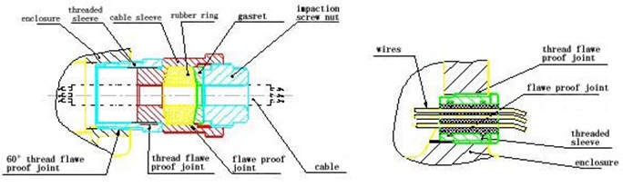
The battery house and the electric house, the electric house and the motor house cable connect with the secondary sealed to ensure anti-explosion performance (see to drawing 3-7).
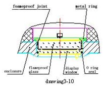 3.2.11.4 The type of explosive proof actuator display window
The interface of the transparence window and the electric cover use the type ”O” sealed ring and sealed glue (this place dose not disassembly or else will be damage explosive proof structure performance), this design structure is according to item 5.4 ﹑5.5 and 8.1 of GB3836.2 (see to drawing 3-8).
In order to the display screen display the character in normal state, the actuator provide four setting places to the LCD screen:
a. actuator level mounting (handwheel towards up); the display screen normal place.
b. actuator level mounting (handwheel towards down); the display screen normal place but the display mode is setting reverse mode.
c. actuator side mounting ( handwheel towards left); the display screen mounting place near the side of flange.
d. actuator side mounting ( handwheel towards right); the display screen mounting place near the side of flange but the display mode is setting reverse mode.
The client should provide the correct mounting mode of actuator while in order, if not, we can provide the field engineering service.
3.2.12 Electronic latching
The electronic latching means inhibits the actuator torque protection function within 5 seconds and allows the motor to generate torque in excess of rated torque to enable operation of jammed valves while starting operation signal is enabled, should the actuator stall when attempting to unseat a valve stuck in its seat, the motor will be de-energised to preventing damage.
3.2.13 Application range
RAⅢ actuators are suitable for intermittent control in automatic control loops that the system rate of change is 600 starts per hour. For the long travel, it should providing the average torque required by the valve in mid stroke does not exceed 33% of the rated torque of the selected actuator. The RAⅢ actuator continual operation time is 15 minutes and motion proportion is 33.3%. If the applications need high start frequency, please select the RAⅢ range actuator.
The basic RAⅢ actuator is Multi-turn electric actuator, it suitable drive the linear motion valve such as gate valve. If client need the big output torque can select RGD gearbox. If the actuator applies to the rotary motion valve, it should match with RGW rotary gearbox. The type of RGD and RGW gearbox are one level reduce rate gearbox, the reduce rate are 40:1﹑60:1﹑70:1, the multilevel reduce rate is more than 80:1. The data of RAⅢ range actuator coupling with gearbox see table 4-4, more detail of gearbox information please contract to us.
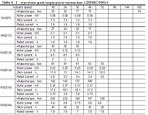
4. Actuator Data
The data sheet includes table 4-1, table 4-2 and table 4-3, table 4-1 in condition of the actuator power supply 380VAC, table 4-2 in condition of the actuator power supply 220VAC, table 4-3 is the actuator coupling interface data.﹡
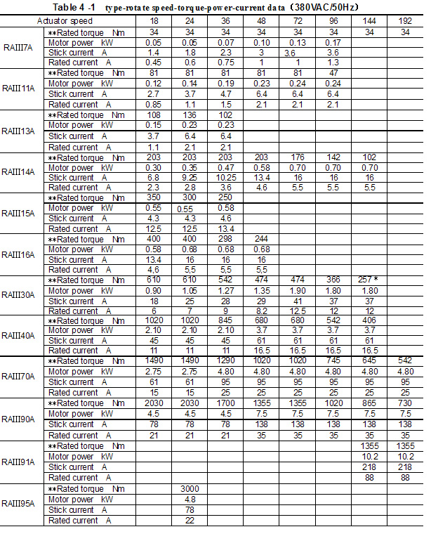 “﹡”:should consider carefully before use these type of RAⅢ range Actuators that have a sign“﹡”in above data sheet, because of rated speed so rapidly to wear machine.
“﹡﹡”:the torque rated is the normal value, user can setting the maximum torque protection value which is 1.2 times of the rated value.
“﹡”:the torque rated is the normal value, user can setting the maximum torque protection value which is 1.2 times of the rated value.
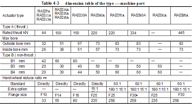
* :In case of RAⅢ90A coupling with B3、B4, may be chooses flange of F25。
**: User choose the reduce ratio of handwheel according to the valve travel time and number of operator.
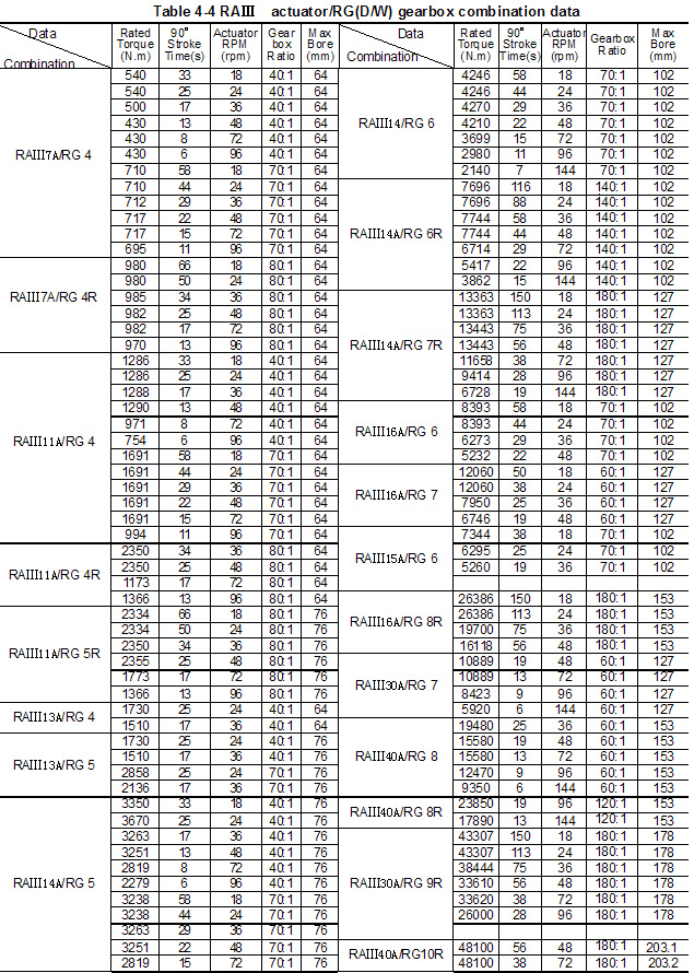
Note: *: RG represent RGD or RGW, **: the travel time specify the 90°rotary motion time of RGW, ***: it means the multilevel gearbox of reduce ratio included and above 80:1
5. Actuator Performance
5.1 Torque and position
■ position setting range: 3.5 to 2040 turns, with a minimum angular resolution to 11.5°of actuator output center column.
■ torque switch setting: 40% to 120% rated torque.
■Electronic latching time: about 5 seconds
5.2 Cable entry and connecting terminals
■The sizes of middle cable entries is and M40×1.5 and the side of two is M25×1.5
■The sizes of four power terminals are M5 and the number is 4 of 380 VAC(3 of 220VAC)
■The sizes of control terminals are M4 and the number is 47.
5.3 Drive bush base data
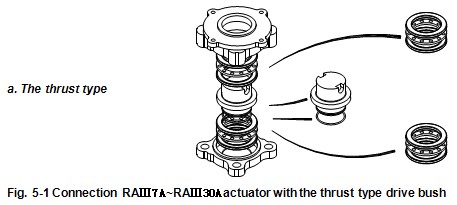
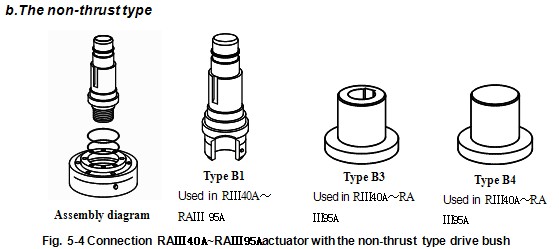
There are two type of the RAⅢ actuator drive bush base, RAⅢ7A~RAⅢ30Achoose the divided base, RAⅢ40A~RAⅢ95A choose the combination base. The two bases are with ISO
5210 standard. The coupling of actuator and valve has two modes that are the thrust and the non-thrust. The type of thrust drive bush is type A and type Z3, the type of non-thrust drive bush is B1、B2、B3. The shape of drive bush see to figure 5-1 and figure 5-2, the size of installation see to figure 5-3 and 5-4.
5.3.1 Type A drive bush
The type ‘A’ is the thrust type drive bush that couples a fully sealed and lubricated thrust bearing to guarantee which have not any load effects on the actuator inner structure.
5.3.2 Type Z3 drive bush
The driving shaft bored and key are designed according to ISO 5210 standard. And the type B non-thrust bush has three basic form as follows B1, B3 and B4. Refer to Fig. 5-1.
5.3.3 Type B drive bush
The driving shaft bored and key are designed according to ISO 5210 standard. And the type B non-thrust bush has three basic form as follows B1, B3 and B4. Refer to Fig.
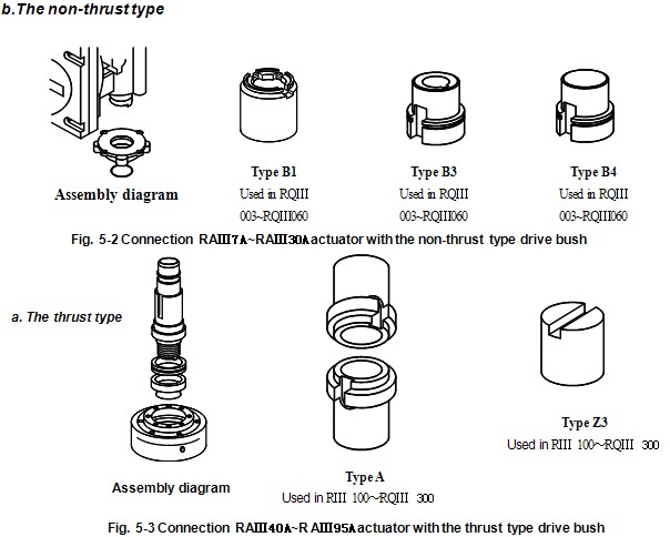
5.3.4 Type B1 drive bush
Type B1 supplies a big bore and key to coupling the valve.
5.3.5 Type B3 drive bush
Type B3 supplies a small bore and key to coupling the valve.
5.3.6 Type B4 drive bush
The size of type B4 is the same as type B3 but not supplies the bore and key to the user, it needed to be machined to suit the input shaft of the gearbox or valve that it will drive.
If drive the outside stem that should select the type A drive bush. In condition RQ003~RQ060 of actuator couple with the valve by the drive bush type of B3 or B4, if the valve stem move along with the axis direction. The coupling interface as following.
5.4 Mechanical vibration
The RAⅢ range actuator normal vibrational frequence is 10HZ to 200HZ and the acceleration of gravity is 0.5.
5.5 Shell watertight enclosure and explosion proof standard
Type waterproof :IP68, according to standard《GB4208-93》
Type explosion proof: Exd II BT4, according to standard《GB3836-2000》
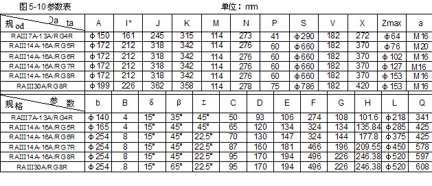
5.6 Mounting data
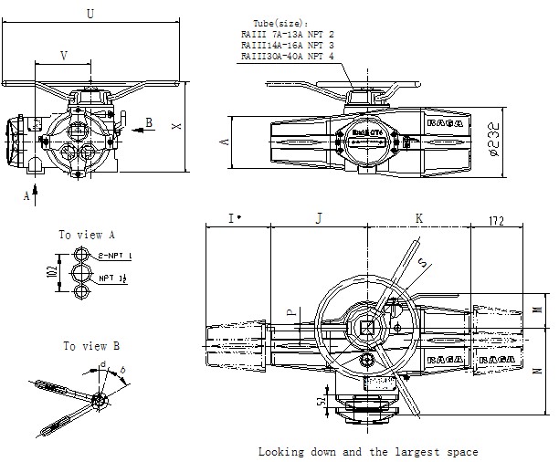

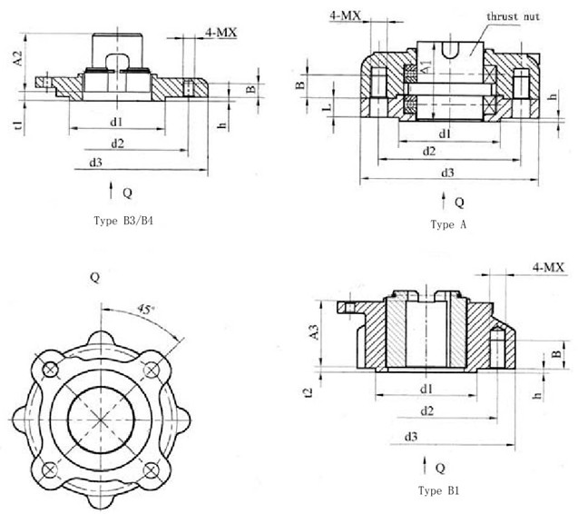

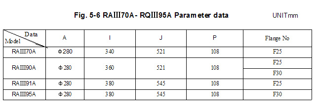
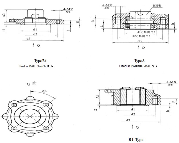
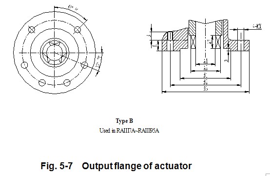
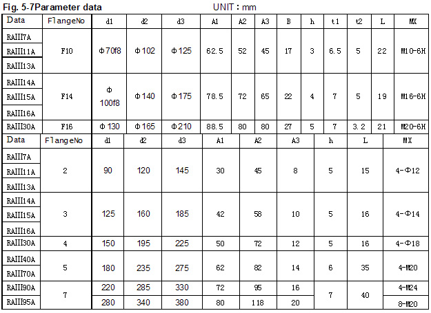
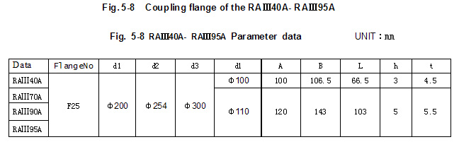
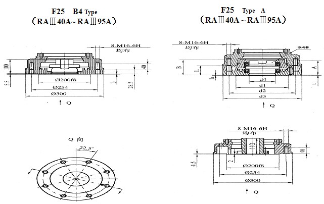
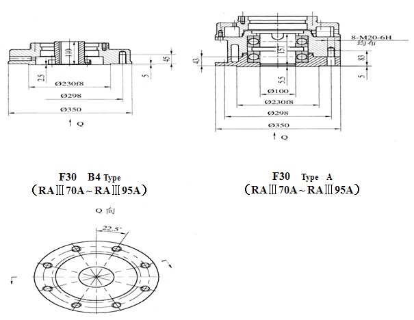

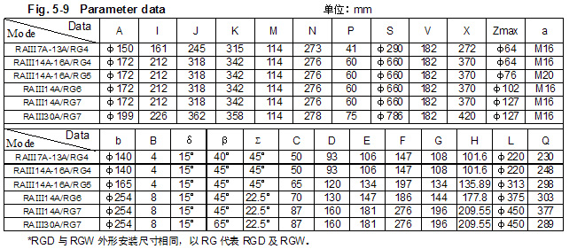
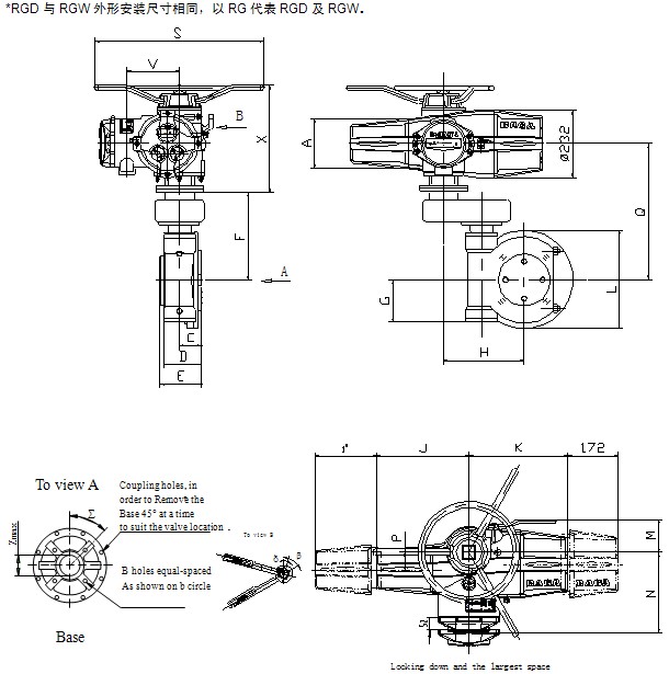
图5-10 RGD/RGW蜗轮箱(二级减速)与RAⅢ执行机构组合尺寸图
6. Actuator Control
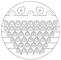 The wiring code card fixed in the terminal cover is
particular to each actuator. The RQⅢ actuator wiring code,
please refer to Fig. 6-1. The means of each terminal refer to
the Table 6-1.

Notice: Mark of “*” items is only used in type of extended mode actuator.
6.1 Local controls
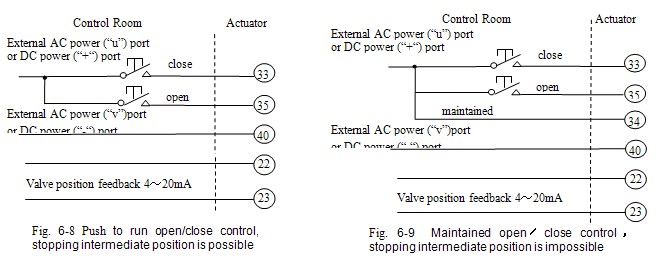
Two knobs are provided on the actuator electrical control cover, one for local/stop/remote selection, and the other open/close control. Local control may be configured for maintained or push to run operation.
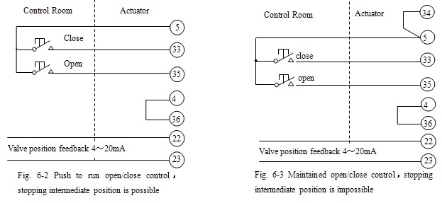
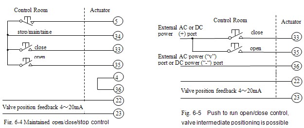
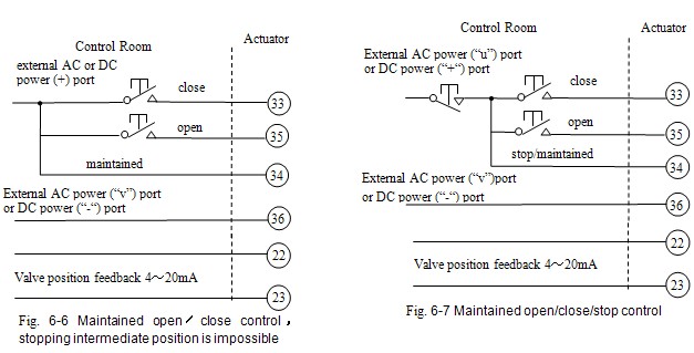
6.2 Remote manual controls
The power supply for remote control circuits are provided as DC 24V by actuator internal supply or DC/AC 24V~60V, DC/AC120V~220V by external supply (all the numbers shown in the Fig. means the terminal port number). Shown circuit Fig. 6-2 to 6-4 were DC 24V actuator internal power supply, Fig. 6-5 to 6-7 were DC or AC 24~60V external power supply, Fig.6-8 to 6-10 were AC 120~220V power supply.

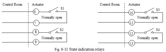
6.3 State indication relay
Four state indication relay are provided, each one independently configurable using the RQⅢ setting tool to signal one of the following:
■ valve position
Fully open, fully close or any intermediate positions
■ status
Valve opening, closing, moving
■ valve alarms
Motor tripped on torque when open, close, valve jammed
■ actuators alarms
Each contact can be configured to either “normally open” or “normally close”. Contacts are rated at 5A/250VAC or 5A/30VDC (see Fig. 6-11).
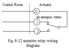 6.4 Monitor relay
An independent relay with a volt-free changeover contact used for monitoring actuator electrical availability. Contact rating 5A/250VAC or 5A/30VDC.
The relay will de-energise under a one, or combination, of the following conditions:
■ loss of one or more of the power supply phases
■ loss of control circuit supply
■ loss of bus communication
■ motor thermostat tripped
■ mode switch is not at the remote position
Refer to Fig. 6-12.
6.5 Emergency shut down ( ESD)
An active ESD signal will override any local or remote control signal. The ESD input operates from a separate common to that used for open, close.
The following ESD options can be configured:
■ ESD signal
Active high, active low
■ ESD action
Close, open, stay-put
■ ESD override
Motor thermostat ,stop,interlock,2-speed
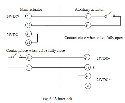 6.6 Interlocks
External hardwired interlocks for opening, closing or both directions can be configured to inhibit local and remote operation until the external contacts are made. Interlock circuits may be added with any of the remote control circuits. The interlock inputs operate from a separate common allowing for isolation between the safety system and operation control system
(refer to Fig. 6-13).
6.7 RAⅢ actuator extra functions optionr(efer to Table 6-2).
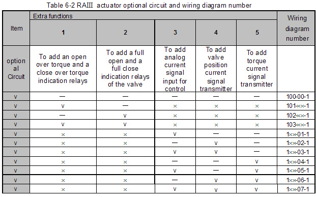
NOTE:“—”means you do not select; “√”means you already select。
Example: If you selected 1,3,4 functions, the wiring diagram number is 201-03-1。
6.7.1 Extra relay
The extra relay option provides four additional changeover relays. The extra relay functions are show below:
■ Valve position fully open
■ Valve position fully close
■ Close over torque
■ Open over torque
6.7.2 Analogue signal input Module
The analogue signal input board provides a non-contacting internally fed 4~20mA analogue signal proportional to valve position. Available at terminals 22 and 23, the maximum external impedance that may be connected to the signal is 500 ohms at nominal supply voltage.
Analogue signal input impedance:
4mA~20mA/250 hm;1VDC~5VDC/1M ohm;2mA~10mA/250 ohm;0.5VDC~2.5VDC/1M ohm
6.8 Analogue signal control
The RAⅢ actuator analogue signal proportional controllers enable the actuator to automatically position a valve in proportion to an analogue current or voltage. A signal derived from the actuator non-contacting position sensor is electronically compared with a signal proportional to the input signal. The difference between them triggers the open or close contactor in the direction that will cancel the error. Valve position is therefore automatically adjusted in proportion to analogue signal. Unnecessary frequent operation can be prevented by the adjustable deadband and the Motion inhibits Timer features.
■ action on loss of input signal: stay-put, move to high or low signal position. Response on loss of signal will occur if signal falls below 50% of set “low” signal.
6.9 Fieldbus control
6.9.1 Modbus communication
Signal or dual MODBUS modules may be included in the RAⅢ actuator to provide remote serial communication to the control functions and for status feedback data. The field network uses an RS485 data highway, either 2 or 4 wires, and can be duplicated where redundancy is required. The communication is half duplex and the protocol used is Modbus RTU with data rates up to 38 K baud. The actuator variables necessary to set up the system are programmable over the infra-red data link.
Modbus module advantages:
■ cable cost reduction
■ installation cost reduction
■ simple to configure
■ simple to use
■ widespread open standard protocol
■ many compatible devices available
■ redundant configuration available
6.9.2 Profibus communication
Pofibus connectivity is possible by fitting the DP interface module within the RAⅢ actuatoe. this allows the RAⅢ actuator to be integrated into a standard Profibus network. Full compatibility with the fieldbus standard EN 50170 is provided and the module carries Profibus certification for inter-operability. The network allows full control of the actuator and feedback of status data to the host. The RQⅢ actuator Profibus module has two communication ports to facilitate redundant fieldbus wiring where reliability is paramount, data rates up to 1.5 M baud are supported.
Profibus module advantage
■ cable cost reduction
■ installation cost reduction
■ simple to configure and use
■ devices independently approved
■ widespread open standard protocol
■ large number of compatible devices available
■ redundant configuration available
7. Order Introduces
Model designation must be noted the each item, for example the wiring diagram number means the actuators versions, and if you require order a gearbox, you need to fill upon its model number.
■ Actuator model number
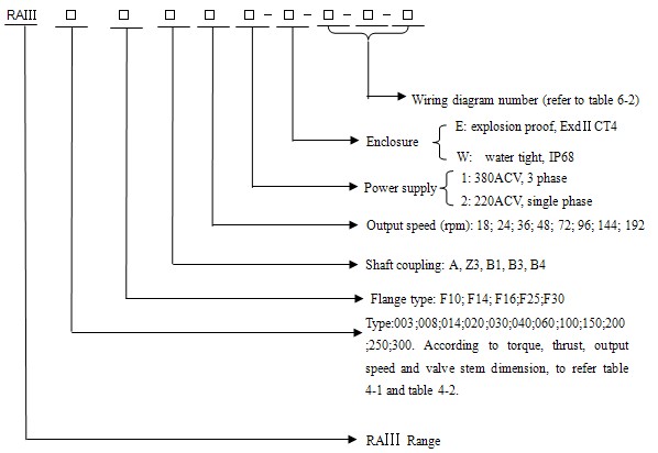
Example: RAⅢ16AF14A-24-1-W-101-03-1
Means: actuator rated torque: 400N.m; flange type: F14; drive bush type: A; output speed: 24; Power supply: 380ACV; enclosure: IP68 water tight; appending analogue signal input, valve position signal feedback, battery low alarm relay, remote control select alarm relay and thermostat tripped alarm relay.
■ Gearbox
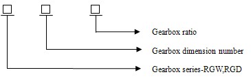
Detail information can be found on the corresponding tecdata sheets.Example: RGW5- 40: 1
Means: RGW range ; dimension number: 5;gearbox ratio: 40:1.
Even if the actuator and gearbox are provided all together, the model of the gearbox is not marked on the identification plate of the actuator. There is an individual identification plate on the gearbox; on it marked with model of the gearbox and so on.
Addendum:Selection Illumination of The Actuator
You can select the actuator’s type according to the following parameters:
1. The max. torque and adjust torque for the valve: The max. torque (if need you can add the appropriate insurance coefficient) is the rated torque of the actuator that you select. The adjust torque is the required torque when the valve is adjusted normally.
2. Moving speed of the valve----the rotate speed(rpm) of the actuator’s output shaft. If you know the stroke of the valve S (mm) , the stroke time T (s) and the lead of the valve-stem screw thread L (mm), then:
Output shaft rotate speed=60S/TL (rpm)
According to the rated torque and output rotate speed, you can confirm the dimension No. of the actuator primarily with the table 4-1 and table 4-2.If the time of the full journey is longer (more than 10 minutes, for example), you must figure the average torque of the valve during the actuator is running and check that if the average torque is more than one third torque of the selected actuator, if it is more , you must select the bigger type actuator. In the most conditions, you can only consider the rated torque.
3. Link mode of the flange
According to the material use occasion and valve-stem dimension, you can select the appropriate link mode. Please refer to the table 4-3.
4. Parameters of the valve-stem
The valve-stem external diameter of the worm drive is not the same as the key drive. You can confirm the actuator primarily according to the 1 and 2 parameters, then according to the table 4-3, check that if the external diameter is satisfied with the requirement of the valve-stem external diameter or not. If it is not satisfied, you can only select bigger actuator.
5. The required max. axial thrust of the valve
If this value is more than the rated axial thrust of the actuator primarily selected above (check the table 4-3), you must select the actuator has bigger axial thrust. Notice: here the rated torque of the actuator is determined by not the max. axial thrust of the drive-nut but the machine intensity of the concerned parts. When you use the drive-nut on the primary valve, you may not consider this value.
Important notice: in order to advance the orientation precision, popularly you do not select the exorbitant output rotate speed. Here’s a advice : the time of the full journey is not less than 25 seconds.